Factor correction pf Complete auto power factor panel wiring diagram What are the components of a substation
The circuit diagram of the single-phase power factor correction system
Automatic power factor compensation for industrial power use to What is power factor? formula, disadvantages & causes of low power Power factor controller wiring diagram
Power factor correction schematic diagram
Power factor simulation diagram electronics basics, electronicsPin by konok kamruzzaman on engineering science in 2021 Power factorWazipoint engineering science & technology: electrical power factor in.
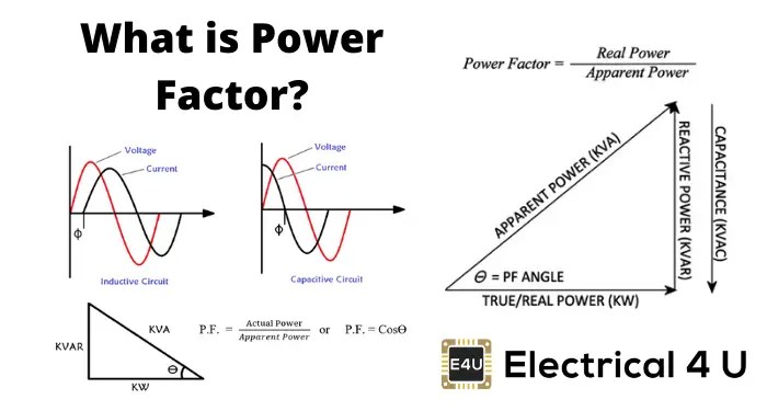
Power factorPower factor diagram formula circuit circuitglobe Power factor correction circuit diagramWhat is power factor (cosθ) ? cos fi or p.f definitions & formulas.

Power factor and power factor correction, pt 2
Power factor: improvement & correction methodsPower factor panel power wiring diagram Factor lagging inductorFactor power.
Factor power electrical diagram schematicDiagram pfi circuit Factor correction digikey automatic schematicPower factor penalty diagram compensation minimize automatic industrial use electrosal block.

Power factor reactive calculator
Power factor wiring diagram control relay controls relays default summary menus settings factoryPower factor explained Power factor correction capacitor wiring diagramPower factor meter.
Power factor controller circuit diagram using pic microcontrollerThe circuit diagram of the single-phase power factor correction system Power factor circuit diagram.Factor power using controller automatic pic circuit microcontroller diagram correction capacitor apfc control microcontrollerslab choose board.

A deeper understanding of power factor
Factor correction capacitor pfInside the capacitor bank panel: power factor correction, calculation Power factor control relay cxplusWhat is zero power factor method.
Rlc parallel circuit (power factor, active and reactive power2: circuit diagram of power factor improvement and controller Factor power correction diagram wave explained poor mindset engineeringPower factor wiring diagram.

Factor power schematic electrical diagram formula
Automatic power factor correction unit price13: circuit diagram for current and power factor measurement Connection power factor correction capacitor wiring diagramPower factor tutorial.
Power factorFactor power formulas cos triangle fi reactive apparent active electrical true complex examples explanation ac circuit kva cosθ kw diagram Wazipoint engineering science & technology: electrical power factor in.


Inside the capacitor bank panel: Power factor correction, calculation

power factor controller circuit diagram using pic microcontroller | Pic

The circuit diagram of the single-phase power factor correction system

RLC Parallel Circuit (Power Factor, Active and Reactive Power

POWER FACTOR CONTROL RELAY CXPLUS

Power Factor Wiring Diagram | PFI Wiring Diagram | Power Factor wire
Power Factor: Improvement & Correction Methods | Electrical4U